Briefly Splitting My Attention
Posted by Zack Spellman
In which I am distracted by microcontrollers
This will be a bit of a braindump of everything I've learned over the
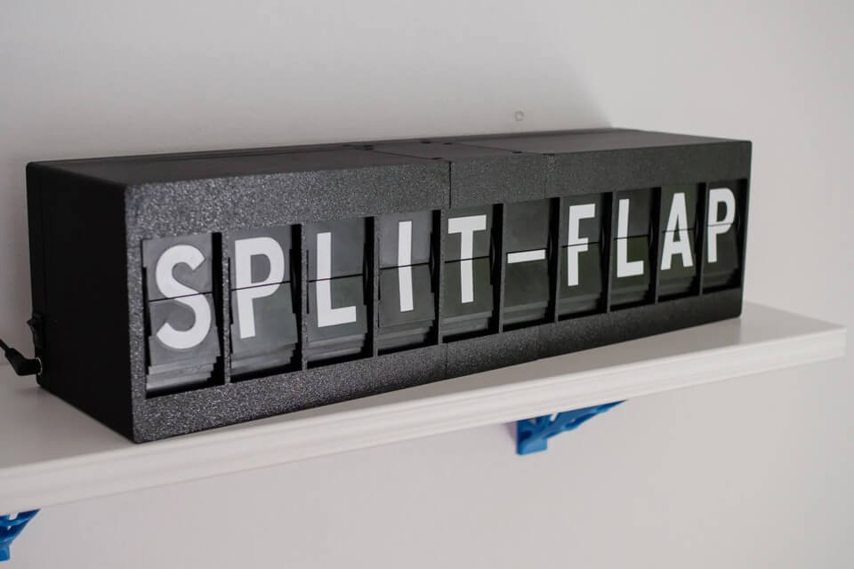
past 48 hours. Tl;dr investigation into building a split-flap display
led to a deep dive into microcontrollers, stepper motors, I2C, and
something called avrdude. Everything I know is pretty surface level at
this point, but it's a large surface that I barely knew existed, and
I'm absolutely fascinated.

I was chatting with my wife and was curious what we had on later in the day, so I glanced over at our Skylight (a wall-mounted tablet with calendaring features) and realized that I was too far away to read it. This led to one of us joking about needing something more analog like a split-flap display for at-a-glance "what's next" uses. Given our recent successes with our 3d printer, this led to the question: could we make one ourselves? Were there pre-made designs out there?
This fairly quickly led to a number of open source designs, and what quickly became apparent was that the housing and flaps were the easy part of the display. The real cost (time, money, complexity) was in the electonic components - a stepper motor, a driver chip, a hall-effect sensor for finding 0 degrees of rotation, and a microcontroller to tie it all together... per letter. And that's before we consider wiring, PCBs, solder, resistors, capacitors, and reliable power supply.
There are some excellent tutorials and schematics online about how to tackle all this, so if I was content to simply follow along with what someone had done before me and my goal was a functional display ASAP, I could probably do that in about six weeks. The lead time for parts is about three weeks, and then assembly and printing would eat up the rest of the time.
But that would require running someone else's code without really understanding it, and I wanted to know more about how it worked.
Stepper Motors

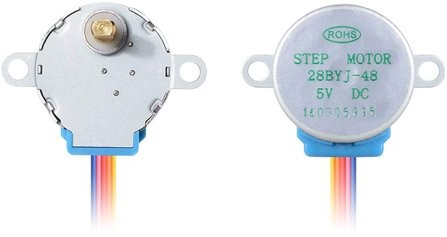
I knew from brief previous forays into robotics that a stepper motor was fit for purpose, and tutorials agreed with me. What I didn't know was that you drive a stepper motor by activating four electromagnets in sequence around the center. Each full sequence rotates the rotor some small number of degrees (like 1/64th of a revolution), and most stepper motors are internally geared to trade speed for torque and accuracy (like 1:64).
What really blew my mind is that you are responsible for generating the activation pattern - 1, 2, 3, 4, 1, 2, 3, 4 - and holding the last one so the rotor doesn't get turned by other loads. This means you can drive in reverse, you can stop at quarter cycles, and you control the speed. The last one is scary - go too fast and resistance on the rotor will prevent enough rotation from happening and make the rest of the cycle useless. I'm still not sure how to detect that is happening.
Stepper motors are used in so many applications that they are quite cheap and relatively standardized. They're used in cars, appliances, and CNC tools. I'm seeing 28BYJ-48 units for about a dollar or two a unit. There appear to be other standards as well, and to be honest I could spend a lot more time here understanding other options and how they work, but as nothing else immediately appears at such a low price point it's hard to believe I can do a lot better.
Darlington Transistors
To drive those electromagnets, you typically need a higher voltage than your microcontroller will emit on IO pins, so you need a way to amplify the signal. I had worked with MOSFETs before, but the designs I was seeing used a ULN2003 chip, which turned out to be a package of seven Darlington transistor pairs. These turn out to be slightly better suited for this specific application, and they're cheap - one of these seems to be about fifty cents.
Arduino

The big surprise for me was that most homebrew split-flap designs then turned to an Arduino board to generate the activation pattern. Going into this dive, I'd assumed there'd be another purpose-built chip that you supplied an instruction like "turn to 60 degrees", and it would generate the output pattern from there. I think there's two challenges I didn't appreciate:
- You don't just "send" an int on a single wire
- Storing instructions requires RAM
So you use a microcontroller.
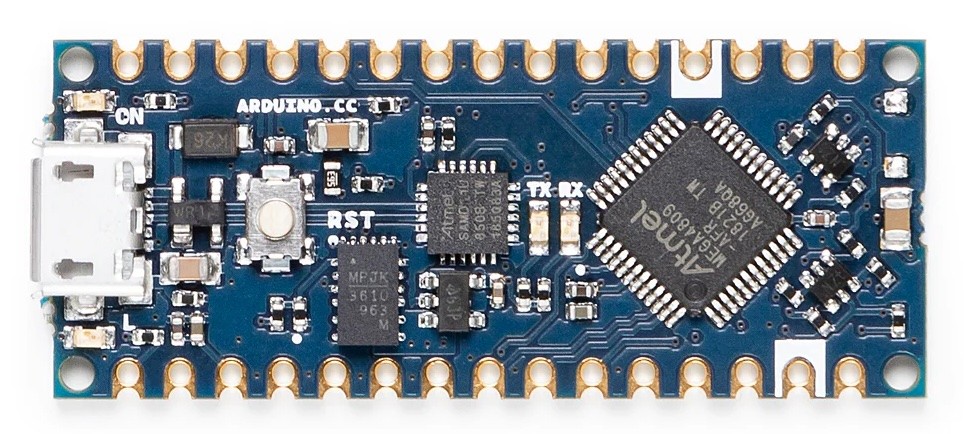
But Arduinos aren't exactly cheap. They're fantastic for prototyping, and this dive has taught me a lot more about why that is true, but having to have a separate Arduino board for each letter on the display was going to balloon costs - the cheapest board I could find was $14. When you're looking at building a display with 50 letters, suddenly every dollar matters a lot more.
Luckily, the bill of materials on the first sample project I found had already solved this: just buy the chip instead.
Microchip, Amtel, and AVR

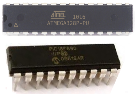
That bill of materials indicated use of an ATmega328 chip. This thing was the real gold mine of this exploration - a 16MHz 8-bit computer with 2KB of RAM and 32KB of instruction space for $1.50. Not only could this thing be trivially programmed to emit the signals needed to drive the stepper motor, it could join an I2C network and receive instructions on what letter to display, and have IO pins leftover for any other sensors I might need.
The manual for this thing is intense - 460 pages of specifications, right down to the electrical characteristics of each component. It's like the TIS-100 manual but for real life (thanks Zachtonics!)
At the same time, you can get these chips in a format where you can stick it on a breadboard and test "simple" programs like blinking an LED, so it seems very hands-on when prototyping. It really makes me wish I'd been able to play with one of these when I was breadboarding in my teens.
For reasons, the program most people use to program these is called
avrdude, an open source program from 2003 (and actively maintained
since) that supports all sorts of chips from Microchip/Amtel. When
I was last doing design at this level (CS 371?), this was always a
bit of a mystery to me - how does my compiled code get onto the chip.
Between the manual and this CLI, it feels a lot more tangible to me
now. Maybe I just have an affinity for CLIs.
I2C, or TWI
The last neat thing I learned was I2C, a protocol for serial communication along a shared, two wire bus. Often called a Two-Wire Interface (TWI) since I2C is I guess proprietary to Philips, the sending party is responsible for emitting a clock signal on one line, and prefixes messages with a 7-bit address to identify the recipient. Then data is sent one byte at a time. It's not hecking fast, somewhere in the 100kbit/s to 3Mbit/s range, but it's really simple to wire.
Closing thoughts
Between 3d printing filament costs and the components listed above, we're still under $10 a letter. I'm sure there's lots of stuff I'm overlooking, plus time isn't free, but that helps with back of the envelope calculations - a homemade display is probably going to cost something like $1000. As someone this inexperienced with stuff like this, that puts it firmly in a "second project" territory. Learning this much has inspired some other ideas, though.
A huge thank you to the following resources for sharing their work and inspiring this very fun exploration. I'm definitely keen to give back if / when I do get to building my own things.